Ackerman- what
it is, what it does and why we care.
A short
history: In the early days of automobiles, no one could make a (4) wheel
car steer correctly. Cars were often driven on wooden floors in the early days
(demonstration purposes only- they were not yet practical anyway) and the
versions with 4 tires were always leaving rubber marks behind. Tire life was
terrible and the cars would often buck as they were turned; this is why there
were so many three wheeled cars initially. The problem was known- as a car is
driven in a circle, the inboard front tire (assuming it is front wheel
steering) must make a smaller turning radius than the outside front tire. This
is evident from tire tracks after a snowfall, a car turning in a circle will
leave two distinct circles, one smaller than the other. This was not an easy
problem to fix because each tire will be the inside the circle at some time and
as the turning radius is changed, so too must this differential change with it.
Enter one Mr. Ackerman- he proved his geometry using bedroom doors and a piece
of string. Much later in time this principle was applied to automobiles. Sure
enough, it works perfectly. All cars since that time have Ackerman built into
the steering wheels as a necessity and it is not subtle; turn the wheels
to full lock on any car (while stopped, of course), step in front of the car
and note the direction the tires are facing. The inboard tire will be turned
significantly further than the outboard tire; reverse the direction of the turn
and Ackerman reverses also.
Ackerman is
rotary to linear differential. For those who know what a cosine curve looks
like, Ackerman simply moves the link between rotary movement away from X = 0.
The most intuitive example of Ackerman, at least to me, is any piston engine.
Notice that while crankshaft speed is constant, piston speed constantly changes
from maximum near 90 degrees to <zero> speed at the top and bottom of the
stroke. This is also the Ackerman principle at work.
I must confess
to misusing the term. Ackerman is the specifically the geometry found on the
steering end of cars. I have applied it to the control surfaces of model planes
erroneously- it's a misnomer. However, I can't think of another word that
describes it so well....
For a visual example, look at
the circle below: 
This drawing shows two
symmetrical points, each offset 15 degrees from the centerline, or 15
degrees away from 90 and -90 degrees. This is how Ackerman is introduced into
our control systems. When this wheel is turned, anything attached to these
points and held at -0- degrees (horizontal) will not move the same distance.
See below:
And here it is in a nutshell-
Ackerman has made the linear distance different between the top and bottom.
Notice that the wheel was rotated 15 degrees, and the top linear distance was
0.113 inches but the bottom distance is only 0.105 inches. This is what
Ackerman does. Ackerman is dependent on the initial angles chosen- if +/- 90
degrees are chosen (that would be the top and bottom center of the circle),
there is no Ackerman introduced and all linear motion will be the same for both
points. The angle that will generate max. Ackerman is 45 degrees. This examples
uses 15 degrees so that it's easy to see but in practice, we would normally
choose something more reasonable for a pull-pull system....
The reason Ackerman works as
it does is because any point attached to a disk that rotates makes both
horizontal and vertical motion. In other words, a clevis attached to a rotating
control arm will move both back and forth, but also up and down. What Ackerman
does is alter this relationship; using Ackerman, we 'trade' some of our
fore-aft movement for up-down movement, which we don't care about. This is
exactly where the slack comes from..... the cable going slack is doing so
because it's also moving closer to the pivot point (on a horizontal line). If
this is not clear, try to visualize the movement that occurs between the two
drawings above; the upper cable is moving a greater distance left - right than
the lower cable is but the lower cable is moving a greater distance up - down
than the upper cable is. Effectively, we are trading this up - down motion,
which we don't care about, for a differential left - right motion, which we
certainly do care about.
The next part in understanding
the application of Ackerman is seeing where this circle and connection points
is found on our toy planes. It would initially appear that there are no circles
used as all we use are servo arms and surface control horns but this is not
quite true as a circle can be drawn around any three points. This means that
there really is a circle around both the servo arm and the control surface. As
most servo arms are straight and therefore symmetrical, we can't easily
introduce Ackerman at the servo end of the system so it has to be used on the
'other' end of the system. Look at the next picture for a visual reference as
to how and where Ackerman is introduced into our toy planes.
This is a typical control arm
installation. We can draw a circle using the hinge line as the center, and
sweeping right through the holes that the clevises (clevi?) attach to. The red
line is shown for reference between the holes in the control horns. This
drawing isn't the best but the forward flat part would represent the horizontal
stabilizer, the aft portion would be the elevator, and the horns / clevises are
shown mounted directly above and below the hinge line. This mounting scenario
has NO ACKERMAN. It is fully symmetrical and will be absolutely linear. As one
cable moves rearward, the other cable moves forward the identical distance.
The next view should make
Ackerman usage clear:
The horns have now been moved
rearward 0.140 inches in relation to the hinge line. Note the red lines- these
indicate the angle formed between the horn holes and the hinge line. As the
bottom cable moves forward to deflect the flight surface downward, the upper
cable will move rearward but NOT AS MUCH as the bottom cable moves forward. It
is a distinctly asymmetrical system. This is also positive Ackerman; moving the
holes in the control horns forward would create negative Ackerman, and this
would be disastrous.
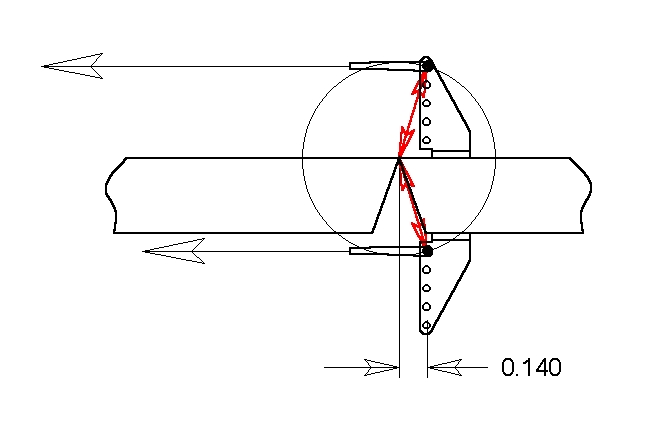
Now watch what happens when
this system is deflected: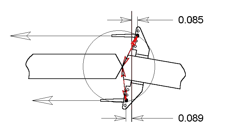
The control surface has
been deflected 10 degrees but the cable travels are not equal- there is a
.004" (inch) difference between the upper and lower cable movement. This
will introduce exactly that amount, 0.004", into the non-pulling side of
the cable, which is the upper cable in this case. Of course if the deflection
is the other way (up), then the differential will also be the other way.
It also does not matter which
side has the slack- as the airflow will always force the deflected surface
toward the neutral position, the nature of the forces involves actually chooses
which cable is taut and which is slack.
One other critical
consideration: The pull-pulls must be centered around the hinge line rather
than some other geometry like the center of the surface being controlled. This
is not a consideration with pushrods but MUST be compensated for if using an
offset hinge line. Consider the example below:
This is exactly the same as
the example above it but the hinge line is now on the top. The cable connection
point must be placed so that the hinge line is the geometric center instead of
the surface. Notice that the circle is centered at the hinge point and that the
red arrows still indicate that each cable is the same distance from the hinge
line. This causes the geometry of the cable system to go right out the window;
each cable will not be straight but actually at an angle. More importantly,
they will be at different angles. This is a prime example of using Ackerman-
this system would be virtually impossible to compensate for if constant tension
was the goal but using a bit of Ackerman will fix it up perfectly. The cables
will now gain slack at slightly different rates but we don't care about this. A
constant tension system would almost certainly result in a tight point
somewhere other than the neutral (center) point.
I firmly believe that many
people actually introduce Ackerman into both pull-pull and pushrod control
systems without ever knowing that they have done it. Usually, the control horn
is mounted behind the hinge line because of the bevel on the surface itself. In
fact, this is how I found out I was using it..... I installed (2) pull-pull
systems with great results (and Ackerman, although unwittingly) and then a
third but that system became tighter as it was deflected (the dreaded anti-
Ackerman :-) ). After sitting down and thinking about this for a while,
blinding comprehension took hold. As a kid, I had read about Ackerman and his
geometry; a gust of clear thinking made me realize that I was using it on my
model, although by mistake and in one case, incorrectly.
A few points on using
Ackerman. It is not really desirable, but it is a wonderful tool for making
absolutely sure that the tightest point in the entire servo (and controlled
surface) travel is the neutral point. Slack in the system is not the goal;
having the system NOT tighten as it moves away from neutral is. So how much
Ackerman do we use, how do we measure it and is it critical? Not much, we
don't, and no, it's not. I do not measure any angle or differential when
I use a pull-pull system but rather 'cheat' by simply offsetting the control
horns a small amount. In other words, when I install the horns, I simply line
up the leading edge of the control horn with the hinge line and then move it
back (aft) a slight amount, perhaps 1/16" to 3/32". I do not measure
it but know that there is some Ackerman installed, and <some> is enough.
This 1/16" or 3/32" (that's about 1.5 or about 2 mm for you metric
types) is the measurement from the hinge line to the clevis holes on the horn;
no other measurement matters.
There could certainly be too
much Ackerman introduced during construction but this isn't likely. If the
cables were attached in such a manner as to create a 30 or even 45 degree
angle, then the slack introduced during deflection would be far too much, far
too soon. That said, look at drawing #4 again and see how likely it is that
this would happen- not very likely. With 3/32 inch of offset behind the hinge
line, the cables will remain tight through approximately 10 degrees of
deflection. After that, there is sufficient force on the deflected control
surface, even at zero forward speed, due to prop wash. In fact, I do this all
the time in the hover; the plane is not moving but the controls are all
deflected a small amount.... no flutter because even if Ackerman causes a loss
of tension in one cable, the prop wash will provide more than adequate force to
hold the pulling cable taut.
There are apparently some that
have the view that Ackerman, and the resulting slack in the non-pulling cable,
will allow all manner of disastrous things to happen, starting with the
destruction of the flight surface so controlled, and apparently ending with the
death of all living things on planet Earth :-) Well folks, it just ain't
so. It isn't necessary to understand the mathematical relationship to see that
this will work quite well. One easy test is to put your hand out a car window
while driving down the road- start off with it flat and horizontal, then rotate
it a few degrees so that the wind is trying to lift it. Now drive with your
hand in that position until the wind pushes it down or doesn't push it at
all..... it won't happen. Compare this to a deflected surface- there will be no
condition that would push a deflected surface the <wrong> way, or vary
enough in pressure to cause flutter or any other undesirable condition. The
important thing to remember is that once a surface is deflected even a small
amount, one cable (the 'pulling' cable) is doing all the work while the other
is nothing more than 'along for the ride' at that particular time.
Pull-pull controls are the
best thing to hit model planes since sliced bread (which didn't hit model
planes but was quite a step forward in it's own right :-) ). They work
superbly and have no downside. Ackerman provides the icing on the cake so that
pull-pulls become very easy to install and use. Ackerman also is a thing of
beauty without downside provided it's used in a reasonable amount but even this
is almost assured given normal construction.